Building a QRP Labs 5W CW Transceiver Kit – 30-meter
by N6SX
I know I have too many irons in the fire but many of the people in my lab want to practice their morse so we have all ordered the 30-meter 5W CW transceiver kit from QRP Labs. They have recently started to be used by many contesting hams. We chose 30-meter since there tends to be fewer people on the band, its performance during various atmospheric conditions, and no contesting. Although there is a power limit, we are doing QRP so it doesn’t really affect us. I will be documenting the assembly once it arrives … because of the maker-nature of the board, it takes about two-weeks before they ship it and at that time, you can add another week for shipping.
4 Nov 2018 –
Well, I did receive the kit fairly quickly, but I was waiting on the enclosure for the 40m kit I am working on … just an excuse for not starting 😉
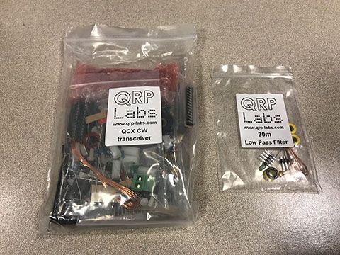
This is what I received from QRP Labs: The parts for the radio is in the bag on the left and the little bag on the right is based on what you ordered. We ordered the 30m version.
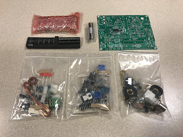
Here is another shot of the parts:
The board:
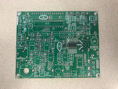
K6TDK and KM6ELK have already started assembling their kits quite a while ago, but neither of them have finished. Partially because they are busy grad students, but mainly because there are quite a few parts all squeezed onto the small little board.
A little side note. You do not need an enclosure, but we kept thinking an enclosure would be a good idea. When we ordered the kits, QRL Labs did not offer an enclosure (they do now), but after K6TDK and KM6ELK saw the enclosure I made for the 40m kit, they suggested I make one for this kit … well, see 🙂
24 Nov 2018 –
In order to get this kit done, I kinda just plowed through the assembly and unfortunately, I didn’t take any pictures along the way. Actually, it was very straight-forward. The instructions are on their website and they step you through the entire process, piece by piece. The only thing that took me a little while is one particular toroid (arrow pointing at it). I’ve had to wire toroids before, but they were always simple ones where I just had to count the number of turns. However, this one needed to be wound in a particular manner. Sooo, instead of continuing to read the instructions, I looked at the picture and chart and started winding … but if you read a little further before starting, they describe a nice easy way to wind this particular toroid. I just didn’t read it until after I had already wound it, oh, well 😛
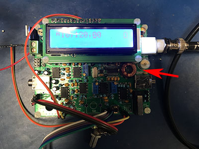
The only change I made was to attach the pots via wires (all the loose wires in the photo are either connected to the pots or are there for future buttons). This was done so I can mount the controls to a future enclosure. They did think about this when they designed the board by including alternate soldering points specifically for wires. I did mount the momentary switches on the board because I didn’t have any buttons on-hand to attach to the wires.
The manufacturer recently started to sell an enclosure for this board. If you decide to use their enclosure, you would mount all the controls (pots and buttons) to the board. Their kit supplies extender pieces that will attach the the control shaft and a shaft that will allow the buttons mounted on the board to be pressed.
I did test the board using an OPEK HVT-600 antenna (thanks KK6MRI for showing me this antenna) and a Kenwood TH-D74 HT to “listen” and everything seems to be working properly.
I am still deciding on whether to design an enclosure or purchasing one from them. The only reason I would want to make one is that I would make it out of acrylic so students can see inside.
If and when I have a chance, I will peruse the websites to see if there are any mods we can apply. If I do find something, I will add it to this page.